Идея улья с вытекающим медом украдена
Откуда идея появилась?
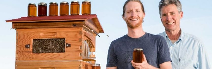
Многим известен, прогремевший на весь мир знаменитый Австралийский улей с вытекающим медом. Изобретатели, отец и сын, Седар Андерсон и Стюарт Андерсон после 10 лет разработок представили миру свой уникальный улей. Казалось, какая отличная идея! И почему никто раньше не догадался до этого? Оказывается, Cedar and Stuart Anderson просто украли идею у Испанского изобретателя Juan Bizcarro Garriga, о чем свидетельствует патент № 288,951 от 08.08.1939 года. Получается, что идея с вытекающим медом из улья уже была в далеком 1939 году и по праву принадлежит Испании. Изобретатель опередил время своим изобретением, так как на тот момент отсутствовали необходимые технологии для массового изготовления подобной конструкции.
Ниже приведена часть патента с оригинальным текстом изобретателя.
ПАТЕНТНОЕ ВЕДОМСТВО США
Улей
Хуан Гаррига Bizcarro, Игуалада, Барселона, Испания
8 Августа, 1939 года. Приложение, Серийный № 288,951
В Испании 21 Апреля,1939
Улей с кассетами изготовлены из металла, был построен в течение некоторого времени. Его предпочтительно изготавливать из алюминия, качество этого металла и его сплавы очень подходят для цели.
При использовании улья с кассетами, по моему изобретению, все операции извлечения меда из ульев значительно упрощены, путем отказа от манипуляций внутри улья. В результате чего работу по сбору меда, который является длинным, утомительным и даже опасным, превращается в короткую и легкую операцию, которая может быть выполнена любым человеком.
С другой стороны, пчелы не раздражены выполняемыми операциями, которые должны проводиться в целях сбора меда, что позволяет избежать сокращение производства количества меда. Все это, в пользу пасечника.
Это следует из улучшений. Извлечение меда может осуществляться в улье без пчеловода, прибегая к фумигации, не надо вступать в контакт с пчелами, тем самым избегая опасности быть ужаленным.
Принципиальная особенность изобретения заключается в том, что клетки (кассеты) состоят из трех частей, две боковые части и третьей центральной части, далее стены матрицы. Матрица стена приспособленные для определенной степени передвижения, относительно боковой или боковой части, которой стены матрицы позволили занять соответствующее положение, в котором мед и содержащиеся в клетках может стекать наружу и проходить к сосудам, который может быть легко удален пчеловодом.
Другие преимущества и особенности изобретения будут в дальнейшем описаны.
Как известно, соты построены пчелами и состоят из очень большого количества мелких сосудов. Ячейки объединены средней стенкой, так, что они соприкасаются друг с другом по бокам, сверху и снизу. Днища являются пирамидами треугольного сечения, стороны которых равны и соединены вместе, равного наклона, так что клетка представляет собой как единое целое, полый корпус шестиугольной раздел снизу, расположение является таким, что дно каждой ячейки действует частично в качестве основы трех смежных ячеек.
Тела клеток образуют два симметричных ряда с отверстиями, ведущими к каждой стороне клеток.
Толщина ячейки в центре стены или стены матрицы, формируя дно клетки и разделение клетки серию от других. Центральная ось каждой ячейки находится на противоположной склонности к клетке с другой стороны, тем самым предотвращая стекание меда, который содержится в клетках.
Изобретение схематически поясняется, в качестве примера на прилагаемых чертежах, в которых:

Рисунок 1-стойка секционная, высота улья сконструированного согласно изобретению.

Рис. 2 представляет собой деталь в разделе вертикальная поперечная в увеличенном масштабе, части двух ячеек.

Рис. 3 представляет собой вид сбоку улья, как мед извлекается из ячеек.
Цифры 4 и 5 теоретических схем на уменьшенном масштабе, показывают взаиморасположение боковых стенок клетки.
Рисунок 6 показывает схематически в модификации.
Оригинальный текст описания конструкции
Далее, подробное техническое описание конструкции улья и кассет в оригинальном тексте автора:
The hive has provided at I the habitation of the bees, above which are provided two series of cells, as at 2 and 3, which are mounted in a wooden frame 4, which is itself mounted, as at 5 and 6, between the walls of the habitation I the said cells being capable of being removed from and replaced in this frame.
According to the present invention each cell consists essentially of three enclosing parts. Two of the said parts 7 and 8 (Figures 4 to 6) form the longitudinal prismatic cavities such as 9, 91, of hexagonal section, and the other part 10, which is adjustably mounted between the first two parts, forms the bottoms of the said cells in — the form of triangular pyramids, the said bottoms being arranged in such a way that those on one side form the bottom of the cells on one side and the others form the bottom of the cells on the other side. The relative positions of these three parts are variable to suit requirements as will be explained hereinafter.
The three parts or members above referred to composing each cell are constructed with the greatest precision, so that by suitably connecting 4g them together, the walls of the cells of the side parts may be extended and their bottoms fit exactly to the matrix or central wall so as to produce when assembled complete cells.
The matrix or dividing wall of each cell (Fig- 55 ures 1 and 2) is mounted on a supporting member 11 by means of a screw-threaded rod 12 which passes through the supporting member 11, and on which is screwed a nut 13 which rests on the supporting member so that the matrix or dividing 55 wall in each case may be adjusted in the vertical direction.
The central or matrix wall 10 which carries the bottoms of the cells corresponding to the side 5 portions 7 and 9 is mounted by means of linkage 14 (Figure 2) on a screw-threaded pin 15, on to the screw thread of which is screwed a nut 16 by means of which it is possible to determine exactly the correct position of the matrix wall 10 with 10 respect to the side walls 7 and 8, so that the longitudinal hollow parts of the cells shall coincide exactly with the corresponding bottoms.
All the matrix or central walls of the cells of a hive are mounted in a supporting member such 15 as i I, so that they can be caused to slide simultaneously as a whole when so desired by the beekeeper.
It is by means of this sliding movement that coincidence is obtained between the bottoms of 20 the cells in each matrix wall and the longitudinal hexagonal cavities of the cells, so that the matrix wall assumes with respect to the walls on either side a position as shown in the cell illustrated oh the right hand side of Figure 2, when the bee- 25 keeper wishes to extract the honey from the cells.
This adjusting movement is shown diagram- matically in Figures 4 and 5. In Figure 4 is shown the position of the matrix wall 10 with respect to the side walls 7 and 8 when the cell is 30 in position to receive the honey produced by the bees, the bottoms of the cells provided in the matrix wall being adjusted to the hexagonal openings of the cells formed in the two side walls.
In Figure 5 the matrix wall has been moved lon- gitudinally with respect to the side walls 7 and 8, with the result that at the positions 17 and 18 the ends of the hexagonal openings such as 9 are uncovered, so that the honey contained in the cells 9 escapes in a continuous stream from 40 the top downwards. The result of this is that the honey automatically flows from the lower part of the cell and for the purpose of collecting it a collecting receptacle !9 (Figure 3) is placed in the hive which has connected to it a curved pipe 20 45 through which the honey flows from the receptacle 19 to an externally disposed receptacle 21 whence it is removed by the bee-keeper.
Each cell is of trapezoidal form as will be seen from Figure 1, so that the cells can conveniently 50 be provided above the part I of the hive.
The invention is not limited to the particular construction hereinbefore described. Thus for example instead of arranging the matrix wall to be movable longitudinally in relation to the side 55 walls, the discharge of the honey from the cells may be effected by imparting a lateral movement to the side walls so as to separate them from the matrix wall in a horizontal direction as indicated in Figure 6. In such case, owing to the 60 hexagonal recesses being separated from their respective bottoms, channels such as 22, 23 are formed,, down which the honey escapes to the lower part of the cell.
In the case shown in Figures 1, 2 and 3 it is of 65 importance to the bee-keeper that the cells should be provided with means for raising the matrix walls as a whole. This can be effected by various mechanisms, one of which is hereinafter described by way of example.
The matrix walls of the cells on each side of the hive are suspended from or connected to the rectangular section supporting members 11, car- 5 ried on rollers 24, 25 mounted at the upper ends of links 26, 27 which are pivoted on spindles and the lower ends of which are articulated at 30, 31 to a horizontally extending bar 32, to which is also articulated at 33 a lever 34 the pivot pin of 10 ; which is located at 35 and which is provided with a knob or handle 38. There is thus formed a system of articulated parallelograms controlled by the lever 34.
By turning the lever 34 by means of the handle 15 36 from right to left, the above mentioned system of articulated parallelograms causes the rollers to rise, thus elevating the rectangular supporting members 11 and consequently the matrix walls of the cells as a whole. By moving the 20 lever 34 in the opposite direction the ma-trix walls are returned to their original positions after the honey has flowed from the cells.
This mechanism may be replaced by any other mechanism which will produce the same result. 25
In the foregoing description no mention has been made of the known practical operations which the bee-keeper will have to employ when using metallic beehive cells, such for example as the covering of the cells with a thin coating 30 of wax so that the bees shall be in their habitual element; when this coating of wax is broken owing to the movement of the cells as hereinbefore described, the bees themselves will instinctively proceed to repair the damage. 35
The invention has been described with reference only to cells made wholly or partly of a metal such as aluminium or alloys of aluminium, but is applicable to cells made of other materials.
I claim: 43
- A beehive including cells for the honey made of a number of fixed parts with movable parts interposed, the fixed parts being set at an inclination and forming the walls of the cells and linkage operated through an operating lever for 45 raising said movable parts out Of coincidence with the lower ends of the stationary parts to permit the honey to flow from the cells.
- A beehive including cells for the honey made
of a number of fixed parts and movable parts go the fixed parts being set at an inclination and forming the walls of the cells and the movable parts being disposed between the fixed parts! and forming the bottoms of the cells and means for moving the bottoms of the cells in a vertical 55 direction out of coincidence with the ends of the •fixed parts to permit honey to flow from the cells.
- A beehive including cells for the honey made of a number of fixed parts and movable parts, the movable parts being set at an inclination and до forming the walls of the cells and the fixed parts being disposed between the movable parts and forming the bottoms of the cells and means for moving the movable parts in a direction away from the fixed parts so as to enable the honey до to flow from the bottoms of the cells.
JUAN BIZCARRO GARRIGA.
Делайте выводы о сходстве изобретения